 2004
2004


The keel
by Johan Kjellander 2004, 2014
January - April
A lot of the time is still spent thinking about what will be the most economical way to build the keelbox. I finally decided to go for stainless steel 316L. I found a supplier who sells sheet metal of this quality with minor surface errors. I bought 4 pieces, 2 that are 1.5X3 meters and 2 that are 1X2 meters. A total weight of approx. 1300 kg and a total price of approx. 40.000 SEK (5500 USD). I made the drawing above for cutting out the 16 different pieces.
A plasma cutter was used for cutting. To the left above are some of the smaller pieces. The keelbox will be bolted to the keelplank through the floors with 20 millimeter diameter stainless bolts. The right picture above was taken while marking the positions of the 10 holes to drill in each of the two keelbox flanges. Each flange is 3 meters long, 135 millimeters wide and 12 millimeters thick. The keelbox will fit between the two flanges in the hole in the keelplank and the flanges of course will be welded onto the keelbox.
Another keeljob is the 75 cm's of deadwood still missing. First I used my large plotter to make 13 drawings in full scale. Then I took the drawings into the boathouse, fastned each to a piece of hardboard and cut them with my new jigsaw. The result is 13 frames that I will use to cut out the deadwood.
Six chainplates are now almost finished. Missing are only the holes for the turnbuckles.
Insurance is becoming a problem. So far I have had the boat insured with the same insurance company as my house but the value of the boat is now reaching a limit when they are no longer interested. I made some calls to other insurance companies and found out that an inspection by an official to establish the boat's current value was needed. I called the Swedish Maritime Adminsistration (SMA) and they sent a man to make the inspection. He was very pleased with the quality of the work so far and wanted to establish a value far higher than I expected. After 2 hours of inspection, studies of drawings, measurements of hull laminate humidity and so on he issued a protocol stating that the work was very well done and that the boat was built in accordance with the designers instructions. The value of the boat in its current state he set to 1 million SEK (130.000 USD).
I have also spent a lot of time this winter together with my son Martin to finish his crosscart. Last week we took a ride for the first time. Wow ! It's like riding a rocket. The weight of the cart is only 190 kg's and the motor is a Yamaha YZ250cc giving approx. 45 hp's. On the picture is younger brother Gustav, lots of fun !
May
Welding the pieces of the keelbox together is a timeconsuming job. I started with the longsides and connected them with the top parts and the flanges. To the right above you can see a complete side finished.
I then placed the two sides on top of each other with wooden blocks between to get the right distance and started adding the remaining side parts. The previous picture shows two of the remaing sides in place, one with a hole for the future hydrualic cylinder responsible for lifting and lowering the ballast keel. By the end of may there is only a few days of welding left, then the entire structure will be cleaned and painted. In june I plan to mount the keelbox in the boat. See you then !
June
The welding of the keelbox is now finished. I used my Kemppi 275 Ampere DC weldingunit and approx. 30 kg's of welding material ! Stainless is rather easy to weld and does not require very high weldingcurrent. I used maximum 105 Amps for 4 millimeter electrodes. A major difficulty with a large construction like this made from 12 millimeter thick stainless sheet metal is that the welding itself will influence the shape of the pieces due to tension induced by the melted metal in the joint shrinking as it cools off. You have to plan the welding procedure carefully in order to control the deformation and you might have to straighten out the metal in certain places afterwords using hudralic jacks or by other means. Being an amateur I'm quite satisfied with the result.
After joining the large pieces I added some small details. In order to make it possible to lift the keel, and then lock it in its upper position and remove the hydraulic cylinder (for service or other purposes) I made a hole in the upper part of the keelbox where i could insert a 75 mm diameter "pin" for the keel to rest on. In order to make this watertight when not used I made a flange with holes for a cover to be screwed on to the flange later.
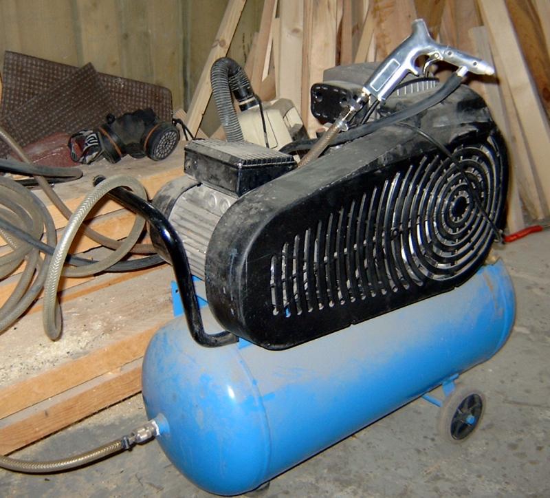
Cleaning the surface of the weldingjoints is important to ensure resistance to corrosion. You can use acid or machine brushing but I chose to try blasting wich worked out well. I used my rather small aircompressor together with a cheap blasting gun from Biltema. By carefully collecting the blastsand and cleaning it I could reuse it several times. The white plastic on the picture was used to keep the sand in the box while blasting the inside.
My original plan was now to paint the entire structure with some epoxisystem but the epoximanufacturer (Nils Malmgren) recommended me not to. Painting would not add anything to give the keelbox a longer life according to them. Contrary, it would only make it more difficult to inspect the surface, which makes sense. A 2 kg Zincanode was added though and according to specialists from the steelcompany this would ensure absolute resistance to corrosion even in very warm and salt waters. Remember that the metal is stainless steel 2343 (316L) or EN1.4404.
After blasting outside and in, it was time to lift the keelbox into position. My friend Tommy who has helped me many times came with his truck and its fabolous crane. I opened the big doors of the boathouse to give access to the boat and then Tommy backed up close to the boathouse and lifted the keelbox up to the aft deck of the boat. He then moved the truck closer to the boat in order to reach further in and lifted the keelbox from the aft deck until it was hanging over the doghouse. We then connected 4 chains and carefully lowered the keelbox down into the boat.
The keelbox weighs approx. 1300 kg, is 3 meters long and 2.3 meters high and there is not much room inside the boat so it took some time and maneuvering until the keelbox was in a position where it is standing on the floor of the boathouse. Next step is lifting the boat 1 meter up in the air so the keelbox will rest on the wooden floors inside the boat. This is how it looks from the outside after lifting the boat half way up.
July
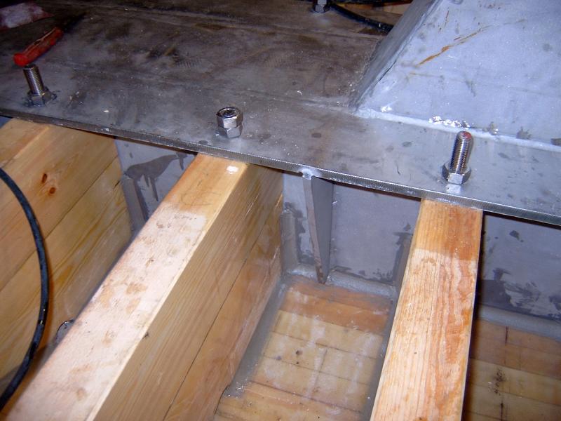
I lifted the boat a total of one meter to give space for the keelbox to come all the way out and still be able to work inunder it. It took some time. 20 keelbolts diameter 20 mm hold the keelbox in place. The second picture above shows one bolt with a 6 mm thick washer seen from the outside and to the right is a picture from the inside.
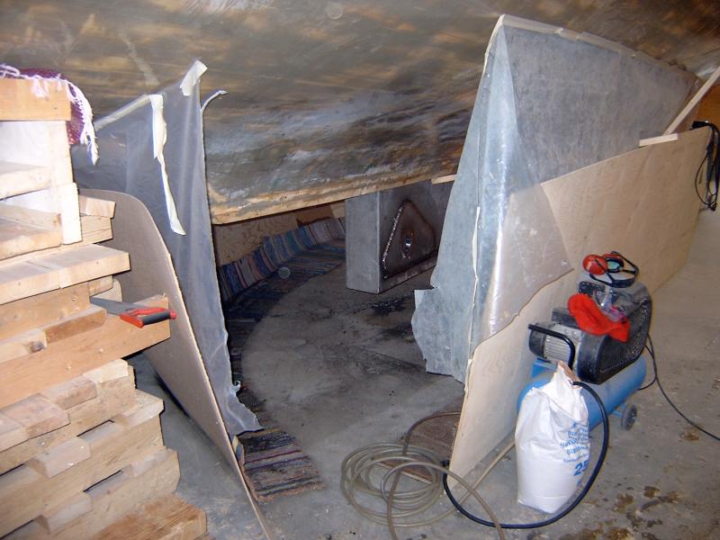
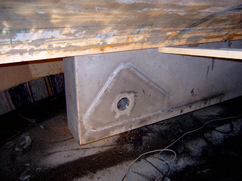
To make the joint between the keelwood and the keelbox waterproof I poured epoxi in between and then added a fillet Once in place there was still some welding to be done on the lower part of the keelbox. To avoid the risc of fire I enclosed the keelbox with plywood, plastic film and old rugs sprayed with water. I then welded on a triangular pivot reinforcement on each side of the keelbox.
To the left is a view from the inside of the keelbox. To check that the pivot was aligned correctly I fitted my laser level with two pieces of plywood onto the pivot and turned it up and down to simulate the movement of the future ballast keel up and down. The red laser spot moved perfectly in the middle of the keelbox, just as it should. Finally I added the rear support for the ballast keel, a 70 mm solid shaft, also from stainless steel of course.
The metal work on the keelbox is now finished and it's once again time to work with wood. To be more specific, the deadwood. I used my new Hitatchi jigsaw to cut out all the 16 layers of 47 mm thick 8 meter long planks. I'm impressed by the capacity of the Hitachi jigsaw. With the right blade it cuts a 47 mm plank just as easy as if it was thin plywood. I then started gluing the deadwood onto the keelplank. This was not a nice job since each layer consists of several pieces and each piece is glued to the underside of the previous layer. Gluing from inunder is never fun and after some hours of work you have a lot of glue on your clothes. The picture to the right shows what it looks like after 4 layers. Getting the deadwood into position will take some time.
It's important with a project like this not to struggle too hard with something you don't like so after 4 layers of deadwood I moved inside the boat and spent some days working with the interior. I mounted the chainplates for good. This is what they look like from the outside. Quite nice, I think. Makes a strong and solid impression.
I then finished the walls to the guest cabin and the floor in the deckhouse. Second picture shows what the deckhouse interior looks like right now. Lots of space as you see. To the right is the guest cabin, to the left is the galley and further aft and up is the deckhouse. Under the deckhouse is the machineroom with the keelbox in the middle and space for one motor on each side.
I have now left the interior to once more struggle with the deadwood. Hope to be able to show you pictures of the completed keel with all the deadwood in position soon !
August
I glued and glued. One layer takes one full day to complete and there are 16 layers to be glued. First picture is 9 layers, second is with 12 layers finished and last picture shows all layers in place. Note the hole for the keel pivot. With the deadwood in place it's time to insert the deadwood bolts. These are made from 12 millimeter diameter stainless steel and positioned in pairs with a distance of 30 cm's. 40 bolts in total, the longest 1.5 meter and most of them around 1 meter long.
People tend to use different ways to set their bolts in epoxi. I invented my own way. Here is how it works: First you close the hole under the deadwood with a piece of plastic film, then you pour epoxi into the hole and then you insert the bolt. When the bolt hits the plastic film in the bottom you quickly remove the film, add the washer and thighten the nut. The result is a bolt completely surrounded by epoxi. I used the same system for the keelbolts. Above is a picture from inunder showing bolts sticking out and the two holes closest to the camera closed by plastic film kept in place by pieces of plywood. It's dirty work and it takes a lot of time but the result feels nice. If you try to unscrew a 12 millimeter stainless steel bolt set in epoxi the metal will break (don't ask me how I know this). Epoxi is a fantastic way to connect wood and metal !
The keelbox is now completely surrounded by deadwood. Above is a picture of the keelbox from inunder looking aft. I aslo added a metal fastener for the lower rudder bearing at the lower end of the aft part of the deadwood. This metal part reaches some 500 millimeters into the deadwood with holes so that 4 bolts pass through it.
Here is a picture from close behind and another picture showing a little more. With all the deadwood in place she is beginning to look like a real boat !
My plan was now cover the deadwood with glassfibre but before doing this i checked the watercontent with my humidity instrument. I was afraid that this years rainy summer had found it's way into the deadwood and unfortunately my feelings were right. The water content was 16%. This is too much to cover with epoxi so I will now leave the keel as it is to dry out during the winter and wait until the water content drops to 12%. This will probably happen in the beginning of June next year.
So, with all outdoor jobs finished for this year I started working inside. I now started in the forward cabin, removed all plywood parts, painted them with one layer of epoxi and glued 50 millimeter of expanded polystyrene on the back side of those pieces facing the hull. The reason is heat insulation and floatation.
Before putting the plywood pieces back for good I have to finish everything else that fits behind them. One such thing is the tubing for the electrical system where I used 16 millineter PVC tubes of the same kind used for electrical systems in homes or industry. There will be a 12 Volt DC system and a 230 Volt AC system. There are also tubes for different instruments or gauges and I also add an extra tube here and there for future use.
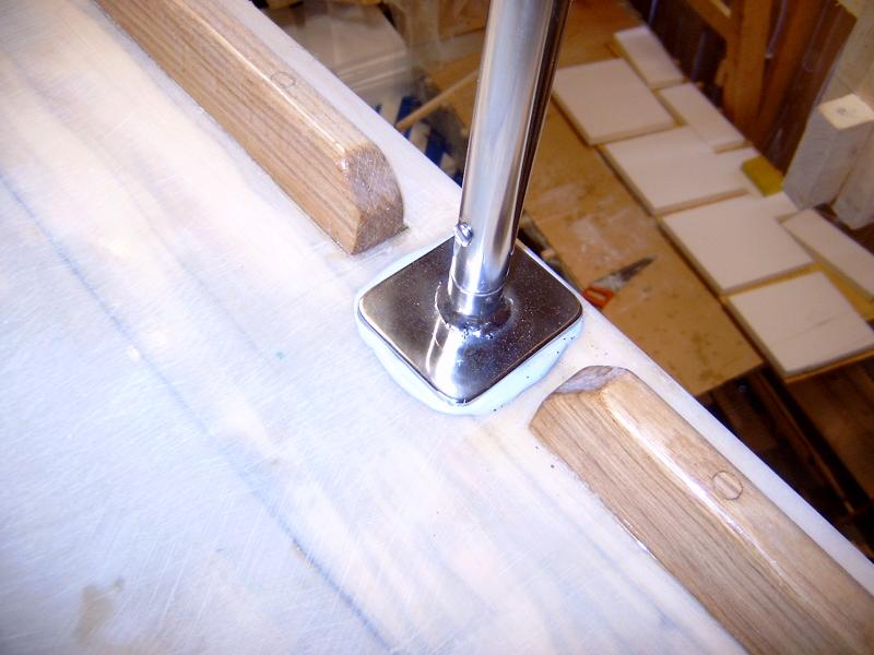
Another thing that has to be finished before putting the plywood back is to finally fasten all deck gear that is screwed through the deck/sheerclamp. One such is the stanchion fasteners. I made these last year (I think) but I never polished them so now I have learned how to polish stainless steel. Not too difficult if you have the right things and the result is really nice !
Winter is now approaching but for the first time I can now turn the heat on inside the boat and continue the work during the winter. I suppose I will go on adding more tubes for the electrical system, add polystyrene to the plywood and so on. I will keep you updated as usual. Next summer will focus on finishing everything outside and then painting the entire deck and hull. If anyone has any good advice on the simplest way possible to add filler, sand and finish the hull and deck surfaces I would be very grateful. Is it possible to use lightweight spray filler of the same kind used for cars (sprutspackel). I suppose this is not epoxi based. What about painting, should i use a roller or should I use my airgun ? I suppose the paint above the waterline will be polyurethane. Below the waterline only antifouling is needed.
September - October
The cold season is here. I have closed the boat, polystyrene foam heat insulation boards in all openings and a temporary door too keep the heat inside. I use a 2.5 kW electrical fan/heater with thermostat. So far it has kept the boat warm and nice without problem.
During the winter I will work with the interior. First step is to put one layer of epoxy on all pieces of plywood. There are hundreds of pieces so this will take some time. Each piece is then sanded lightly. Pieces facing towards the hull side are insulated with 50mm polystyrene foam. The roof gets 20mm of insulation. Final surface treatment will vary between different places in the boat.
Simple surfaces like the inside of lockers and stowages will be painted with a white acrylat water based paint. White is practical because it makes it easier to see what is inside the locker. The forward cabin will also be painted in some light color, maybe a blue tone with dark blue on the hatches. This picture shows some of the parts being painted and next picture shows one of the junior workers with newly painted lockers in the forward cabin.
Flotation is a chapter by itself. One question is how much foam she needs and the other is where to put it. The amount of flotation to make her unsinkable is lees than you might think. Most of the boat is dry wood which is a lot lighter than water. Water and fuel in tanks needs no flotation. Left is things which are heavier than water, the ballast keel, the motors, batteries, rig and so on. Some of this weight will be taken by the wood and the rest needs to be taken care of with foam. My estimate is that 5 cubic meters of foam is well enough to keep her floating.
More difficult is the question of where to put it. It's not that there is space missing, the problem is that most of the available space is in the wrong position to make her float as high as I like. I could go with just the fact that she can't sink but if this means she ends up floating only a few centimeters above sea level this is only a half victory. If she is damaged at sea and filled with water I want to be able to stay aboard, even inside, well protected from rough weather. This means she needs to float much higher than just a few centimeters above sea level. My goal is that the sole of the deck saloon will stay over the sea level at all times. This means that all flotation must be placed lower than the level of the sole in the deck saloon. Under a bed is a good place. The bed in the picture takes foam equal to 250 kg's of floating power. I measure all foam carefully and document everything so I have a record of how much I have and where. So far I have about 1 cubic meter of foam in position low enough. I also have some foam higher up but this foam is not counted as flotation, only as heat insulation.
Work will now continue with more electrical tubing, more pieces of plywood with heat insulation permanently mounted. More flotation in different places, more pieces of plywood painted and mounted and so on until all plywood pieces are finally in place. Hopefully before next summer.
November / December
Most of the pvc tubes for the electric system are now in place, almost 300 meters ! Many of them go to the main control panel close to the indoor steering position. Others go to the 2 main electric central junction boxes in the machine room. Some of the tubes are for the 230V AC system and some of them are for the 12V DC system.
This drawing shows all the tubes, where they go and what they will be used for.
There are two junction boxes in the machine room, the one to the right in the picture is for 230V AC and the other one is for the 12V DC system. The 230V box includes a number of automatic fuses, a 30 mA Residual Current Circuit Breaker (RCCB) and a control lamp that shows when current is available. 230V AC will either come through the shore line or from a 12V DC to 230V AC inverter driven by the boat batteries. The small box with the black handle sitting just on top of the 230V box is a switch that connects the 230V system either with the shore line or with the inverter. The shore inlet is actually 3 X 400 Volt AC so it is possible to feed the boat with quite a lot of electric power when power is available. In many ports however there is only a single 230V outlet available so I will then only feed power through one of the three 400 V lines.
Here is the wiring diagram for the 230V system.
A basic 230V system is now running. This means I can now connect lamps and tools to the boat system and don't need long cables hanging everywhere. This makes life a little easier working inside the boat. It also makes life safer since there is plenty of fuses and also the RCCB.
After having finished most of the electric tubing I now work with the inner walls closest to the hull sides. These are made from 12 mm plywood, coated with one layer of epoxy, painted white and with foam glued to their back sides for heat insulation and flotation. To the right is a view of the aft cabin right now. Note that there is also heat insulation mounted in the ceiling, 20mm. So far I have approx. 1.5 m3 flotation in place.
There are two showers in the boat. One forward and one aft. Both are located on the port side close to the hull but under the raised deck to get full headroom. This means that in each shower there is also space left closest to the hull with reduced headroom. I have spent a lot of time thinking about how to uses these two spaces. The space between the forward shower and the hull will be used to house the washing machine. To protect it from water when using the shower I made a wall with a large hatch that can be opened when using the washer. Under the washer is plenty of space for flotation.
The space in the aft shower will be used for 12 V batteries. Here I made a similar wall with a big hatch and under the batteries is also plenty of space for flotation. The idea is to put the batteries high up enough to be above the water level even if the boat is submerged and only floating on the flotation. In an emergency situation it is nice to have electricity enough to use a radio or other important electronic equipment. There are two shelves in the battery compartment, each big enough to carry two smaller batteries or one bigger. My plan is to have battery capacity in the range of 400 – 500 Ah. The batteries will be charged either by the generator on one of the motors or by a 230 V AC charger connected to the shore line. There will also be solar panels but they will only deliver small currents compared to the generator or charger. A normal generator is capable of delivering charging currents in the range of 40 – 60 amps which is a suitable figure for charging batteries of 400 – 500 Ah. The 230 V charger will have to be quite powerful to charge 50 amps but such chargers are becoming more usual these days and prices are dropping. Generators and chargers delivering 50 amps for many hours will need good ventilation in order not to get overheated.
Ventilating the battery compartment is a special issue. Many modern deep cycle batteries like gel batteries for example are closed and do not normally produce any gas when charged. There are batteries that produce gas however and even closed batteries may produce gas if overcharged so I think it is wise to prepare for this situation. A plastic hose from the highest place in the battery compartment that leads the gas up to a small ventilator outside the boat should be sufficient I suppose. I wonder what dimension to use ? Is 18 mm enough ?


